


Scan-to-BIM Automation: From Five Days of Modeling to Five Minutes of Machine Processing
Published: lipiec 21, 2026
Scan-to-BIM automation uses machine learning to convert raw LiDAR point clouds into structured, BIM-ready geometry, reducing the amount of repetitive reconstruction required from BIM specialists.
LiDAR scanners can capture millions of spatial measurements quickly. However, collecting the data is only the beginning.
Before a point cloud can support renovation planning, facility management, architectural documentation, or digital twin development, specialists must interpret the raw data and reconstruct walls, floors, doors, windows, columns, and other building elements inside BIM software.
The real bottleneck often appears after the scan.
An international survey of Scan-to-BIM professionals found that 80.1% considered manual geometry modeling from point clouds a time-consuming part of the process. Most point-cloud-to-BIM modeling was still performed manually, partly because available automation tools did not work reliably across every building type and project scenario.
This creates a scalability problem for architecture, engineering, construction, reality-capture, and AEC companies: scanning capacity can grow faster than BIM modeling capacity.
Machine learning can help remove part of that bottleneck.
In one point cloud segmentation and BIM conversion implementation, the automated pipeline completed inference and conversion in approximately five minutes in a modern GPU environment. The model achieved approximately 0.85 mean Intersection over Union, or mIoU, across the project taxonomy, with results varying by object class, dataset, and configuration.
These figures describe one project-specific implementation. They are not universal Scan-to-BIM benchmarks or a promise that a complete, approved BIM deliverable can always be produced in five minutes.
Key takeaways
- LiDAR capture is fast, but converting unstructured point clouds into BIM objects remains labor-intensive.
- Machine learning can classify architectural elements and give BIM specialists a machine-generated starting point.
- Segmentation alone is not enough: the output must also pass through geometry reconstruction and BIM conversion.
- Data quality, object taxonomy, hardware, required level of detail, and validation rules strongly influence performance.
- Human quality assurance remains essential, especially for ambiguous, occluded, or irregular elements.
Why point clouds are not yet BIM models
A point cloud is a digital representation of a physical environment made up of spatial coordinates and, depending on the scanning equipment, additional attributes such as color or intensity.
It may reproduce a building with impressive geometric fidelity, but it does not inherently understand the building.
The data does not say:
This is a wall.
This opening is a window.
These points belong to one door, while those points belong to another.
This surface should become a parametric Revit object.
Millions of individual points still require manual or automated interpretation before they can become a structured, usable building model.
In a conventional workflow, BIM specialists inspect the scan and manually reconstruct the architecture. The effort required depends on factors such as:
-
- building size and complexity;
- required level of detail;
- scan density and registration quality;
- the number of object classes;
- occluded or incomplete surfaces;
- irregular architectural elements;
- the target BIM standard and delivery format.
Reality capture scales more easily than manual interpretation.
A business may be able to scan dozens of properties within a short period while its modeling team needs days to prepare each BIM model. As the number of scans increases, the modeling stage becomes an operational constraint.
What “five days to five minutes” really means
“Five days to five minutes” describes the potential change in one part of the workflow. It does not mean that the entire process—from arriving on site to delivering a fully validated model—is completed in five minutes.
A complete Scan-to-BIM project may also include:
- scan planning and data acquisition;
- registration of multiple scans;
- point-cloud cleaning;
- data transfer and storage;
- model training or fine-tuning;
- automated inference;
- geometry reconstruction;
- BIM conversion;
- human quality assurance;
- correction of uncertain elements;
- enrichment with non-geometric information;
- final approval against project requirements.
The five-minute result from Timspark’s published implementation refers to the automated inference and conversion pipeline under specific dataset and GPU conditions.
The comparison is therefore between repetitive manual modeling work and machine processing—not between an entire five-day professional service and a finished model produced with one click.
Scan-to-BIM automation does not remove specialists from the process.
It shifts their effort from reconstructing every element manually to reviewing machine-generated geometry, resolving uncertainty, and applying professional judgment.
How Scan-to-BIM automation works
A reliable system requires more than connecting a point cloud file to a neural network.
The complete workflow usually contains five interdependent layers.
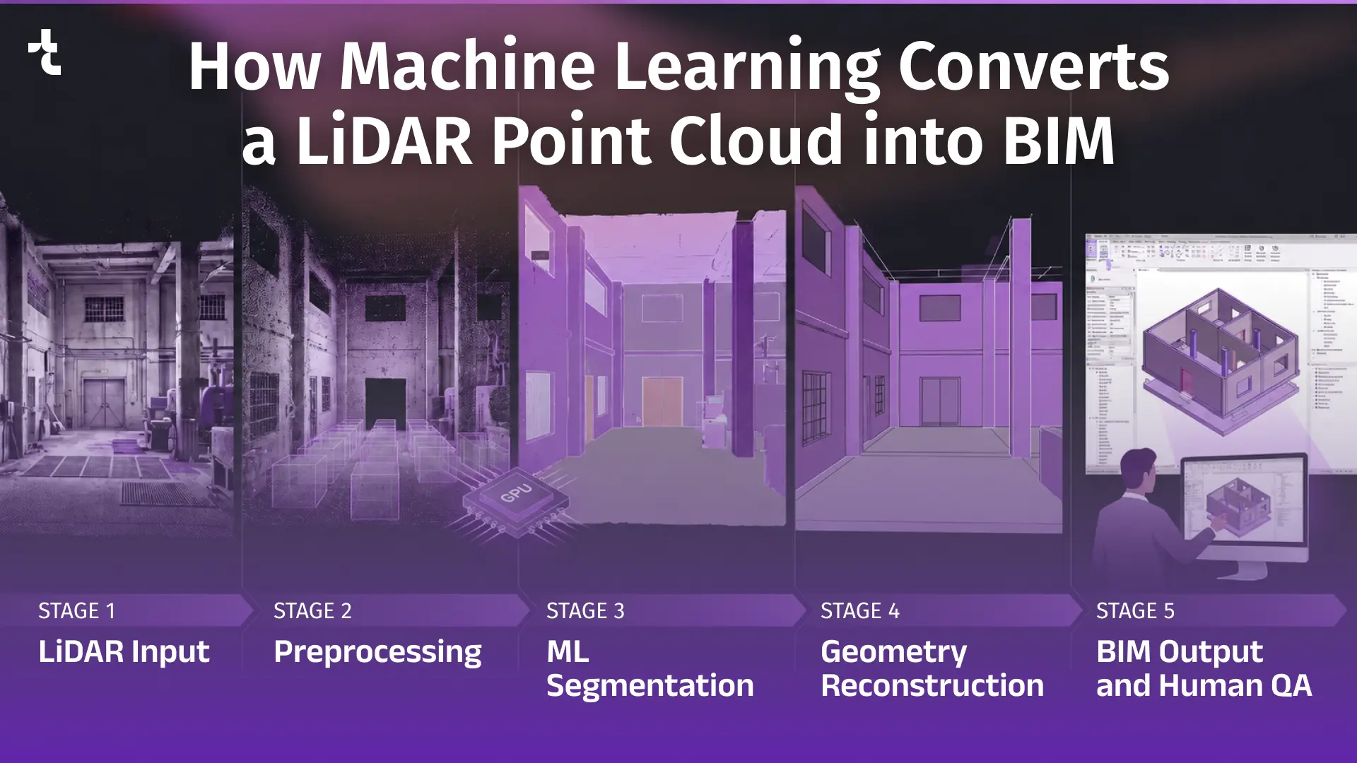
The Scan-to-BIM automation pipeline: from LiDAR point-cloud ingestion and machine learning segmentation to geometry reconstruction, BIM generation and human quality assurance.
1. Data ingestion and preparation
The first challenge is ensuring that the source data is suitable for automated interpretation.
The pipeline receives the source point cloud together with any available labels, project metadata, coordinate information, and reference files.
Inputs may arrive in formats such as E57, PLY, PCD, or other formats used in reality-capture and point-cloud workflows. Large datasets must be stored, versioned, and transferred without losing coordinates or required point attributes.
Before model development begins, the engineering team should evaluate data readiness.
Important questions include:
-
- Are multiple scans correctly registered?
- Is the point density sufficient to reveal doors, windows, and other target elements?
- Are people, vehicles, reflections, or floating artifacts present?
- Are important surfaces hidden behind furniture or equipment?
- Are coordinates and measurement units consistent?
- Is labeled data available for every required object class?
- Does the dataset represent the building types the system will encounter in production?
A machine learning model cannot reliably reconstruct architectural information that is absent from the source data.
For example, if equipment completely hides a wall or an opening was not captured, the pipeline must either infer the missing geometry using predefined assumptions or flag the area for review. Research identifies missing data due to occlusion as one of the principal limitations of automated Scan-to-BIM workflows.
2. Point-cloud preprocessing
Raw point clouds are often too large, noisy, and irregular to pass directly into a neural network.
The preprocessing stage may include:
-
- coordinate normalization;
- scan registration;
- noise and artifact filtering;
- density balancing;
- surface-normal calculation;
- voxel-grid downsampling;
- spatial chunking;
- data augmentation.
Point clouds can contain millions or hundreds of millions of points. Processing the entire building as one scene may exceed GPU memory or make model inference inefficient.
Large environments are therefore divided into smaller, manageable blocks. Overlapping regions can be retained so that the model does not lose important context at chunk boundaries.
Preprocessing is not merely a technical optimization. It directly affects output quality.
If a door is divided incorrectly between two chunks, or if aggressive downsampling removes thin structural details, later stages may misclassify or omit the element.
A review of point-cloud preprocessing for Scan-to-BIM highlights filtering, registration, data reduction, and voxelization as important methods for managing noisy and high-volume scan data.
In Timspark’s published workflow, point clouds were divided into manageable chunks and processed using technologies including Python, PCL, OpenCV, TensorFlow, PyTorch, and the Pointcept framework.
3. Semantic and instance segmentation
Segmentation gives raw spatial data architectural meaning.
Semantic segmentation assigns a class to each point.
Depending on the project taxonomy, the model may recognize:
-
- walls;
- floors;
- ceilings;
- doors;
- windows;
- columns;
- roofs;
- equipment;
- pipes or other MEP elements.
Instance segmentation goes further by distinguishing separate objects within the same semantic category.
A semantic model may recognize that a collection of points belongs to the class door.
An instance model determines that the space contains Door 1, Door 2, and Door 3 as separate objects.
This distinction matters because a BIM model requires individual elements with their own position, dimensions, orientation, identifiers, and relationships to the surrounding architecture.
Modern 3D transformer architectures can learn spatial relationships from labeled point-cloud data. For example, Point Transformer V3 was designed to process large-scale point clouds more efficiently by replacing expensive neighborhood searches with serialized point mapping.
However, architecture selection is only one part of the task.
The model must also be trained on data that reflects the intended production environments. A system trained primarily on regular office interiors may perform differently when presented with industrial facilities, historic buildings, irregular walls, dense equipment, or unfamiliar scanning conditions.
The target taxonomy should therefore be defined by the actual business output—not by the maximum number of classes that can technically be predicted.
4. Geometry reconstruction and vectorization
Segmentation is not the final BIM output.
A segmented point cloud is still a collection of labeled points. Revit and other BIM environments require structured geometry and, ideally, parametric building objects.
The reconstruction layer must convert noisy point clusters into architectural shapes.
Depending on the required output, this may include:
-
- plane fitting for walls, floors, and ceilings;
- wall-thickness estimation;
- line and corner reconstruction;
- boundary extraction;
- detection of door and window openings;
- primitive fitting for columns and other regular objects;
- orthogonalization of intersecting surfaces;
- analysis of adjacency and connectivity;
- conversion of profiles into three-dimensional solids;
- mapping of reconstructed elements to BIM or IFC structures.
Techniques such as RANSAC, principal component analysis, least-squares optimization, concave hulls, ray casting, boundary representation, and constructive solid geometry may be used at this stage.
This is one of the most technically demanding parts of the workflow.
A model may correctly classify most wall points but still produce a cluster that is too noisy or incomplete for direct use in BIM software. The reconstruction layer must turn those predictions into clean, consistent geometry that follows the project’s architectural rules.
Timspark’s implementation included a conversion layer that transformed validated segmentation results into Revit-compatible and BIM-oriented structures. This conversion logic became one of the most reusable parts of the solution for related point-cloud-to-BIM use cases.
5. BIM integration and human quality assurance
A useful implementation should not conceal uncertainty.
Once geometry has been reconstructed, the system must connect it to the client’s BIM, CAD, or digital twin workflow.
Depending on project requirements, outputs may support:
-
- Autodesk Revit;
- AutoCAD;
- BIM 360-based workflows;
- IFC-based exchange;
- proprietary digital twin platforms;
- custom APIs and downstream data services.
The implementation should define:
-
- which BIM objects will be created;
- which properties each object will contain;
- how levels and project coordinates will be preserved;
- what happens to low-confidence predictions;
- which geometry conflicts trigger warnings;
- which elements require mandatory human validation;
- how corrected models return to the operational workflow.
Rather than presenting every prediction as equally reliable, the system can identify low-confidence classifications, incomplete boundaries, unusual dimensions, or conflicting geometry.
Specialists can then focus on the areas most likely to require intervention.
The machine performs repetitive reconstruction. Specialists validate and refine the result.
This human-in-the-loop model is more realistic than unrestricted autonomous modeling and is better aligned with professional BIM quality requirements.
Why segmentation accuracy is not the only KPI
Machine learning projects are frequently summarized through a single accuracy score.
For point-cloud segmentation, mIoU is an important metric because it measures the overlap between predicted classes and correctly labeled reference data.
However, an acceptable average mIoU does not mean that every object class performs equally well.
Large, consistent surfaces such as floors and walls are often easier to identify than:
-
- narrow doors;
- partially visible windows;
- thin structural elements;
- small fixtures;
- overlapping equipment;
- irregular or organic geometry.
A production evaluation should therefore consider more than overall model accuracy.
Relevant metrics include:
-
- mIoU by individual class;
- overall classification accuracy;
- false-positive and false-negative rates;
- geometry quality after vectorization;
- percentage of output accepted without correction;
- average correction time;
- processing time per scan;
- GPU and infrastructure cost;
- end-to-end turnaround time;
- stability across different building types.
The most commercially meaningful KPI may be the number of specialist hours saved per building.
A slightly lower segmentation score may still produce strong business value if the system reliably generates useful wall, floor, and opening geometry that substantially reduces repetitive work.
Conversely, a high average score may conceal poor performance in a critical class.
Business value for AEC and PropTech companies
Scan-to-BIM automation can improve operations in several ways.
Higher processing capacity: More captured spaces can move through the modeling pipeline without requiring a proportional increase in BIM headcount.
Less repetitive work: Specialists begin with machine-generated geometry instead of reconstructing every wall and opening manually.
Faster turnaround: Automated classification and reconstruction can shorten the time between reality capture and BIM-ready output.
Greater consistency: A defined taxonomy and validation pipeline can apply the same interpretation rules across multiple properties or projects.
More focused quality assurance: Confidence scores and geometry checks help reviewers concentrate on uncertain or non-standard elements.
A reusable technical asset: Once the data pipeline, model, reconstruction logic, and BIM conversion layer are established, they can be adapted to additional building types and object classes.
The system is not static. New environments may introduce different layouts, materials, equipment, scanning technologies, or architectural conventions. Models and reconstruction rules should therefore be monitored and refined as the production dataset evolves.
What is Scan-to-BIM automation?
Scan-to-BIM automation is the use of software, machine learning, and geometry-processing algorithms to convert LiDAR point clouds into structured building elements suitable for BIM workflows.
How does a LiDAR point cloud become a BIM model?
The data typically passes through ingestion, cleaning, registration, downsampling, machine learning segmentation, geometry reconstruction, BIM conversion, and human quality assurance.
What does machine learning do in Scan-to-BIM?
Machine learning classifies points according to their architectural meaning. For example, it can identify which points belong to walls, floors, doors, or windows. Additional processing is then required to convert these labeled points into structured geometry.
Is point-cloud segmentation the same as BIM generation?
No. Segmentation identifies the meaning of points, but BIM generation also requires geometry fitting, boundary reconstruction, object creation, metadata mapping, and integration with BIM software.
Can Scan-to-BIM be fully automated?
Some environments and object classes can be automated more reliably than others. Human review remains important for occluded, irregular, incomplete, or low-confidence elements and for confirming that the output meets project standards.
How accurate is automated Scan-to-BIM?
Accuracy depends on the dataset, object classes, scan quality, building complexity, training methodology, hardware, and acceptance criteria. In one Timspark implementation, the model achieved approximately 0.85 overall mIoU, with performance varying by class.
How fast can an automated pipeline process a point cloud?
Processing time depends on the dataset size, model architecture, preprocessing requirements, GPU environment, and conversion logic. In one Timspark implementation, inference and conversion took approximately five minutes in a modern GPU environment. This did not include the complete scanning, preparation, review, and approval lifecycle.
Which BIM tools can support the output?
Depending on implementation requirements, the output can be prepared for Revit, AutoCAD, BIM 360-based workflows, IFC exchange, digital twin platforms, or custom downstream systems.
The future is not “one-click BIM”
The most credible future for Scan-to-BIM is not a universal button that converts every scan into a perfect building model.
Buildings vary widely. Scans contain noise and occlusions. BIM standards differ between organizations and projects. Some information—such as materials, performance characteristics, asset identifiers, or hidden construction details—cannot be determined from visible geometry alone.
The more realistic and valuable future is a workflow in which machines handle high-volume interpretation and reconstruction while experienced specialists supervise quality and resolve ambiguity.
The future of Scan-to-BIM is a faster, human-supervised workflow—not unrestricted one-click modeling.
The leap from five days to five minutes is not about replacing an entire professional service with one inference call.
It is about removing one of the largest repetitive and computational bottlenecks from that service.
At Timspark, we design custom machine learning, point-cloud processing, geometry reconstruction, and BIM integration pipelines around each client’s data, taxonomy, infrastructure, and delivery requirements.
These are project-specific engineering solutions rather than an off-the-shelf Scan-to-BIM product.
Poznaj nasze projekty point cloud segmentation and BIM conversion case study or learn more about Timspark’s Tworzenie oprogramowania opartego na AI, data management and analytics, and Usługi DevOps.